| What's Hot! | Products/ Tools | EFI Tuning | Basic Tuning | Advanced Tuning | Chassis Tuning | Advertise with us |
How to build a Turbo Manifold
Contributed by: Enginebasics.com
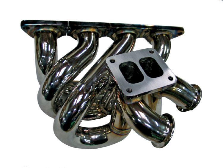
The following is a short article on the steps to take to build your own turbo manifold. The following was build for a 4 cyl motor that was going to be using a divided ( twin scroll ) type set-up. It took roughly 20 hours to build.
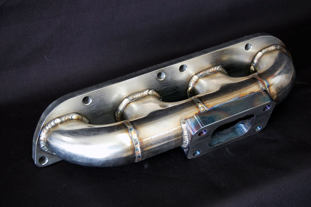
The first thing to do is to get the header flange and the turbo flange that you will be using. Their are many times where a header flange is not offered for your particular engine, in which case you will have to build one. The easiest way is to take an exhaust manifold gasket and trace it out onto ¼” mild steel. Then cut out the design with a plasma torch leaving yourself space to grind down and match the design perfectly after you have cut it entirely out.
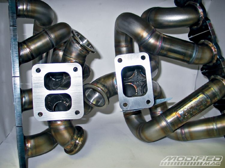
As for the turbo flange, most fabrication companies sell the turbo flanges of the major turbo flange designs. These would be the T3, T4, T6, and Mitsubishi inlets. These flanges should also be purchased in mild steel in ¼” size. Be sure at this point to decide if you need a single entry or twin entry design.
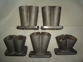
The next step is to construct the collector. Some argue this to be one of the most complicated steps. You must decide not only your collector’s length, but the entry angles of the pipe into the collector. If this is your first manifold that you are building, you may want to purchase a pre-cut collector.

Once the collector is welded to the turbo inlet you can begin to design the manifold. I would suggest using Stainless Steal SS 304L Sch10 Weld El Pipe for a turbo manifold. I have found to have the least amount of cracking going with the thick pipe instead of tube. If your worried about the weight, then using SS tubing can be used, but be sure to use a slip-joint at the collector to help avoid cracking.
STEP 1.
Take some ¼” rod and position the turbo collector where you want the turbo to sit in not only location but angle as well. With the rod, weld the collector in place to the header flange so that between the flange and the collector, nothing will be able to move. Also, be sure to bolt the header flange down to a large piece of metal or a spare head so that as you weld on the flange it doesn’t warp and make it impossible to seal on the engine.
Step 2.
Measure and look for all obstacles that you will have to avoid while building the manifold. Some fabricators will actually tack in small wire to show obstructions to avoid. I usually just construct a design on graph paper showing how much room I have to work with in building the manifold.
Step 3.
Begin to lay out the first runner. Remember that your goal is to make all the runners as equal in length as possible, so the length of this first runner will decide the length of all the runners. Try your best to make the runner have as few bends as possible and to keep the gaps on manifold tight. Do not fully weld the joint but instead tack them in 2-3 places that are easy to get to if you need to break them and make some tweaks or changes.
Step 4.
Lay out all other runners keeping a close eye on the length and bends doing your best to have each runner have the same amount of bends and length.
Step 5.
Now with the fully tacked manifold, place it on the motor and check that everything fits and there are no obstructions. Also make sure there is room to add the wastegate or gate’s on the manifold.
Step 6.
Once completed with all the runners begin planning which runners you will remove to begin welding. On a 4 cylinder I find removing cylinders 1 and 3, or 2 and 4, to give me the most room to weld. Weld the two removed cylinders on a table and weld the other two cylinders runners on the manifold itself. Then weld in the two removed runners to the manifold. Be sure to back-purge the set-up as you are welding so you don’t get sugaring inside the runners and weaken the welds.
Step 7.
Lay out wastegate if building a manifold to support an external wastegate. The wastegate should be placed in the collector where all cylinders have access to the gate. Remember to bias flow to the wastegate or spiking may occur in your boost control. Once laid out fully and tacked, weld the wastegate plumbing onto the collector.
Step 8.
Bolt the turbo and wastegate onto the manifold and make sure everything fits on the engine. Now step back and admire your work of art.
ATTENTION READER:
If you enjoyed the information and article you just read be sure to check out our newly released book with even more exciting photo's and information:How to Turbocharge and Tune your Engine

Want to know more about your particular Make and Model vehicle? All of these vehicles are covered in the tech, maintenance and repair articles found above. Enginebasics is the wiki or wikipedia of car part, repair, how to and tuning information. Let us be the class 101 for your automotive learning.
| Ford | General Motors GM | Pontiac | Jaguar | Land Rover | Nissan |
| Toyota | Honda | Lexus | Acura | Lotus | Scion |
| Infinity | BMW | Mercedes | Mitsubishi | Ferrari | Maserati |
| Lamborghini | Volks Wagen VW | Saab | Audi | Hyundai | Kia |
| Subaru | Mazda | Chevy | Volvo | Caddilac | Dodge |
| Chrylser | Daewoo | Porsche | Mercury | Freightliner | MG |
Individual Models
| Ford Mustang | Mitsubishi Eclipse | Mitsubishi Evo | Subaru WRX / STI | Dodge Viper | Chevrolet Corvette |
| Nissan Skyline | Honda S2000 | Nissan 350z | Toyota Supra | Chevy Camaro | Lotus Elise Exige |
| Honda Civic | VW Golf | Dodge SRT-4 | Eagle Talon | Acura Integra | BMW M3 |
| Nissan 240sx | Porsche 911 | Acura NSX | Honda Accord | Toyota Camry | Toyota MR2 |
| VW R32 | Dodge Truck | Mazda Rx7 | VW Jetta | Sand Buggy | Nissan Sentra |
For the latest Automotive news and stories visit the websites below |
Our feature Build: An AWD V6 Civic


